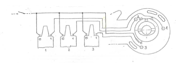
Wartburg 353 and Barkas (12V) and Warburg 311 (6V) electronic ignition with Hall signal installation manual
The electronic ignition includes the power output stage, so there is no need for a separate "black box".
Installation:
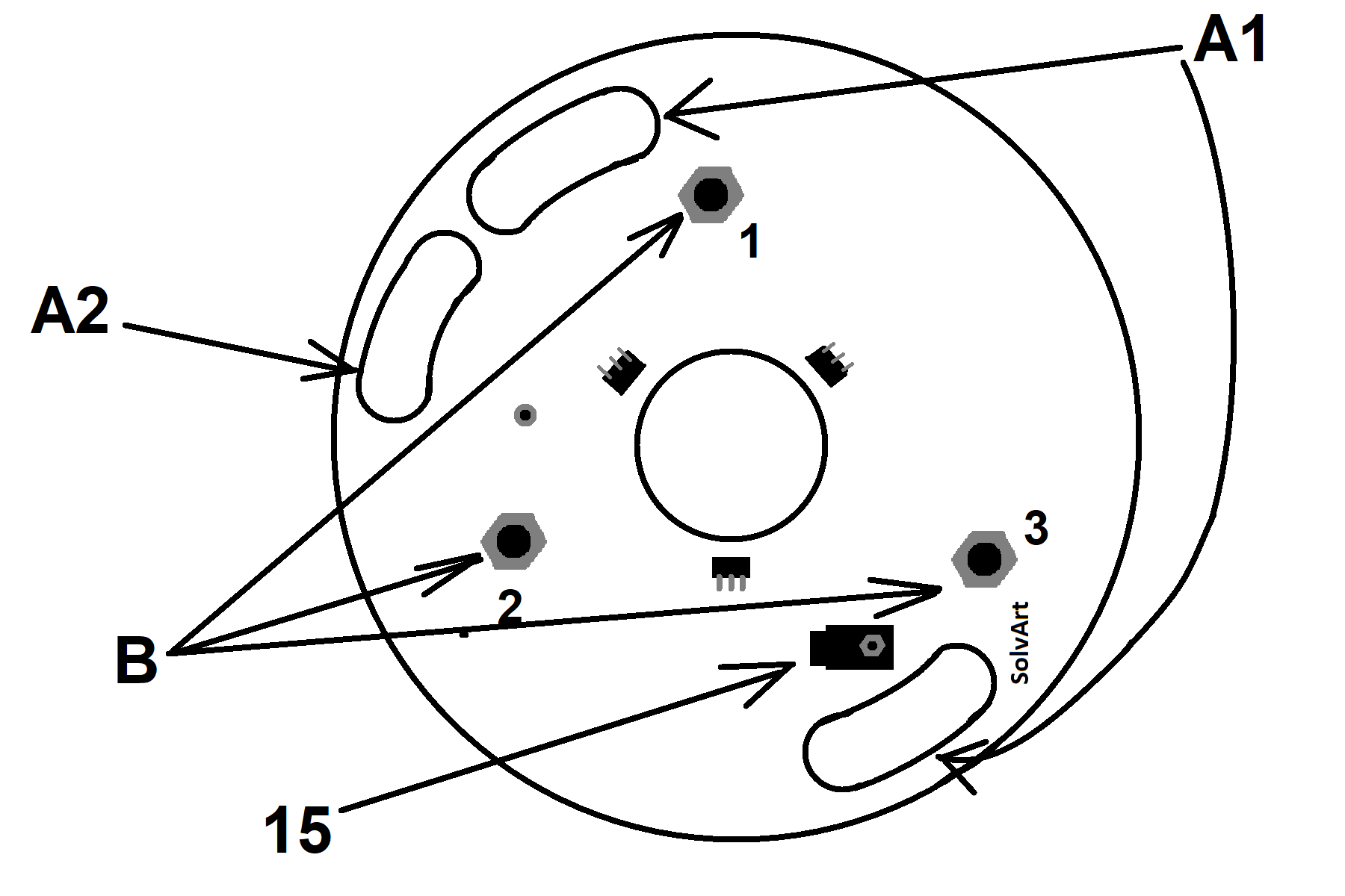
The breaker board must be removed. The ignition board must be installed with the connector pins facing outward. The positioning of the ignition adjustment groove (arrow „A1” – see on picture) and the locator groove (arrow „A2”– see on picture) clearly determine the position of the board.
Attach the cable lugs to the sliding contacts (arrow „B”– see on picture). The number indicates the cylinder indexing.
Lead ignition current (from any ignition coil point) through the wire ( Ø 0.5-1.0 mm2 ) to the sliding contact ( Ø 6.3 mm ) of the board (arrow „15” – see on picture). Use insulating tape or a cable tie to secure the wire to the cable.
Push the attached plastic ring onto the eccentric axis so that the slit faces outward / upward (arrow „C” - see on picture). The slit must fall onto the thicker side in the axis' symmetrical plane. The ring is shaped to fit the eccentric axis, so there is no other way to put it on.
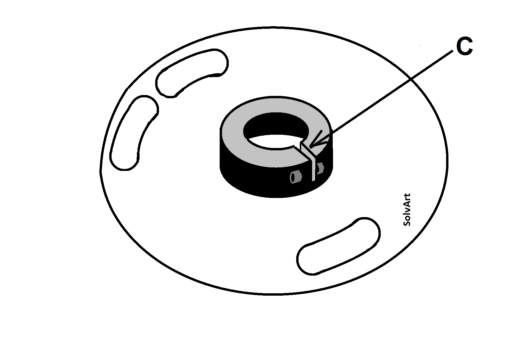
Press the ring onto the axis until it does not touch the board and there is a gap of approximately 1.0-1.5 mm between them. Then tighten the ring onto the axis with the provided Allen key. Only tighten the screw enough to secure the ring. Do not overtighten as the plastic can crack! If the plastic ring needs to be removed for any reason, it can be easily pulled off by slightly stretching the slit (e.g. with a screwdriver)
The ignition time can be set to one of the cylinders (22° top dead point or 3.58 mm) with a strobe light or a test lamp and an indicator clock. The other cylinders is equally adjusted due to the precise geometry of the board, so this does not need to be adjusted separately.
If you manually rotate the crankshaft (test lamp setting), keep in mind that the electronics only work after a full revolution. Always turn the crankshaft in the forward direction, never in reverse, as it will give false values.
Since the board is grounded through the fixing screws, always turn off the ignition before changing the ignition time to protect the electronics. It is also possible to move the ring a little in both directions on the eccentric shaft, this also affects the ignition time!
Protect the board from mechanical damage while adjusting.
The ignition coil remains in its original position. (Only normal coils, which are otherwise used for the breaker system, can be used for electronics. The use of high-performance "transistor" coils is prohibited, and any malfunction resulting from their use is not covered by warranty.) A suitable coil has a primary resistance greater than 3 ohms (current consumption should not exceed 3-4A).
It is also advisable to check the ignition cables. The ignition cable is suitable if its resistance, measured with the cap, is between 5-10 kΩ. This ensures the cable is not broken, and the resistance is not bypassed or short-circuited. The absence of noise-suppressing resistor damping can cause disturbances or even malfunctions in any electronic system, including ignition.
Make sure that the ignition is not turned on when the engine is not running as this can cause overheating and potential malfunction of the electronics and ignition coils. It is also recommended to check the charging system. Overcharging (in the case of a 12V system, when charging above 14.5V; in the case of a 6V system, when charging above 7.4V) can damage both the electronics and the battery.