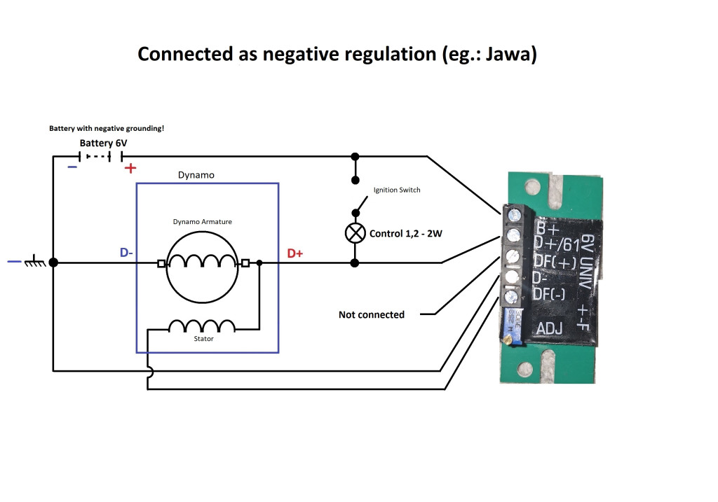
By definition, only one of outputs DF(-) or DF(+) is used in a given case (depending on whether the system has negative or positive regulation). Incorrect connection will damage the regulator.
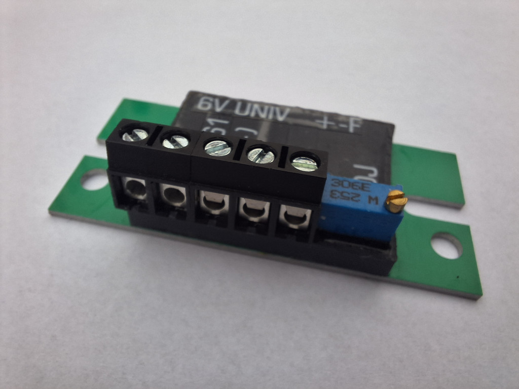
The dynamo regulator works on a 6-volt (6V) system. The regulator is set to 7.2V. This value can be fine-tuned with the trimmer potentiometer next to the terminal.
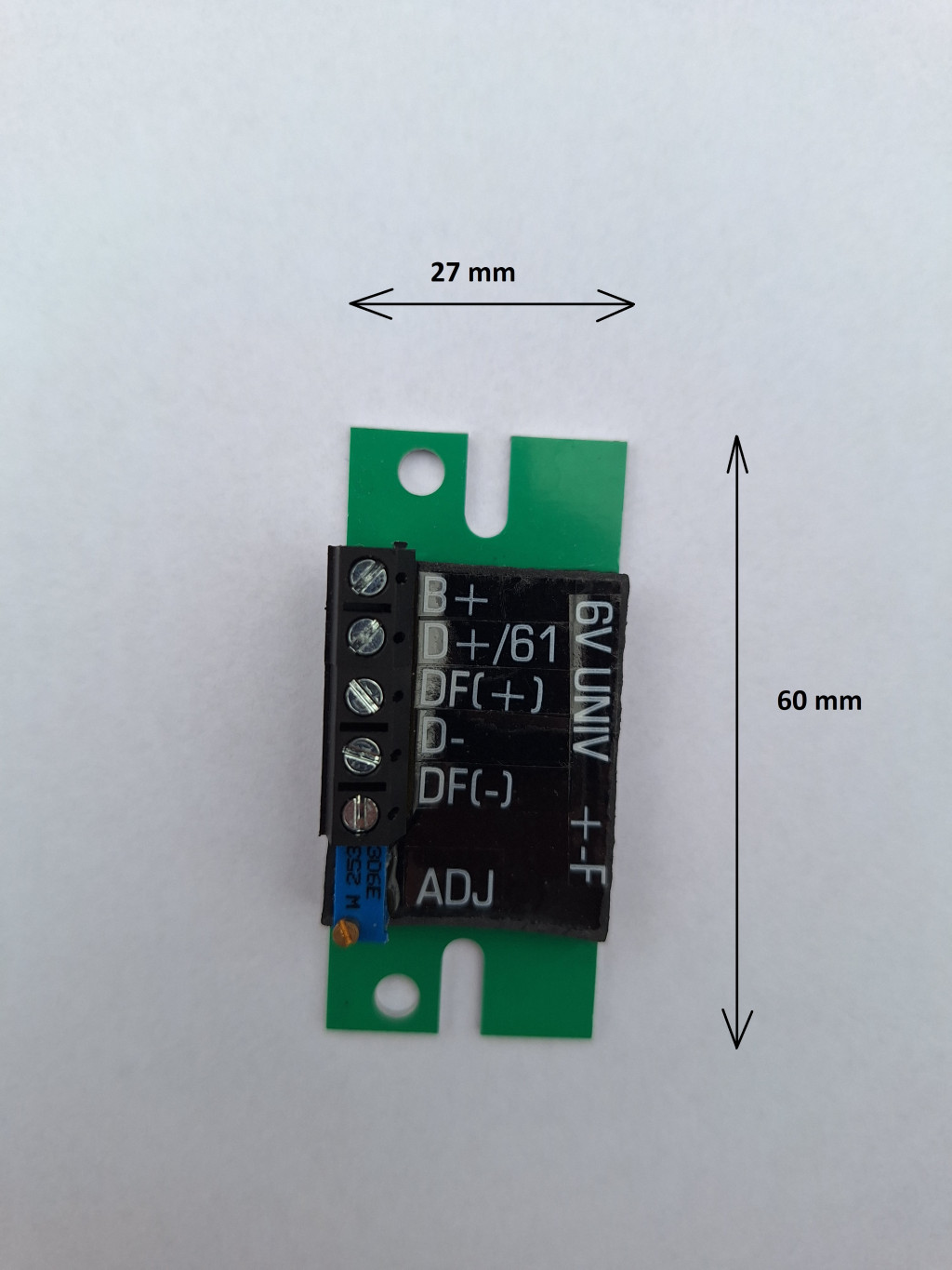
IMPORTANT! The metal plate has been removed from the B+ and D+ terminal blocks to allow easy insertion of 2.5 mm² twisted wires. However, it is important that the stripped ends of the wires are tinned with solder to prevent the screw from damaging the individual strands (Since the metal plate remained in place for the other terminals, it is not necessary to prepare the wires in this way for those).
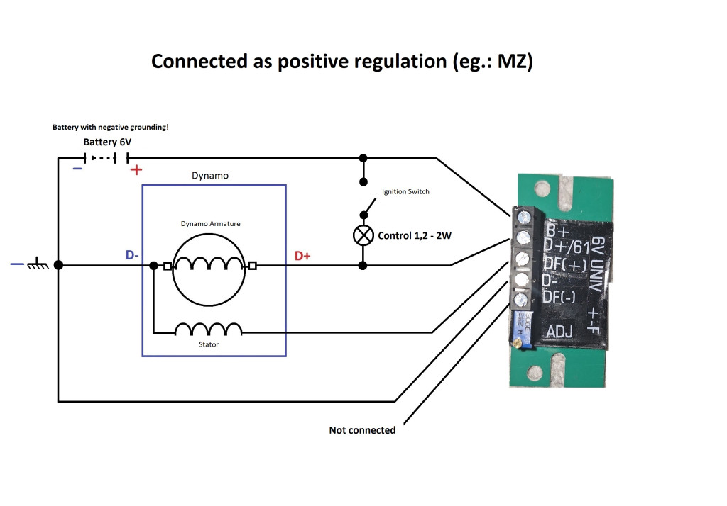
Outputs of the regulator:
| B+ |
battery +6V |
| D+ / 61 |
dynamo armature output / control lamp |
| DF(+) |
excitation for a positive regulation system |
| D- |
negative |
| DF(-) |
excitation for a negative regulation system |
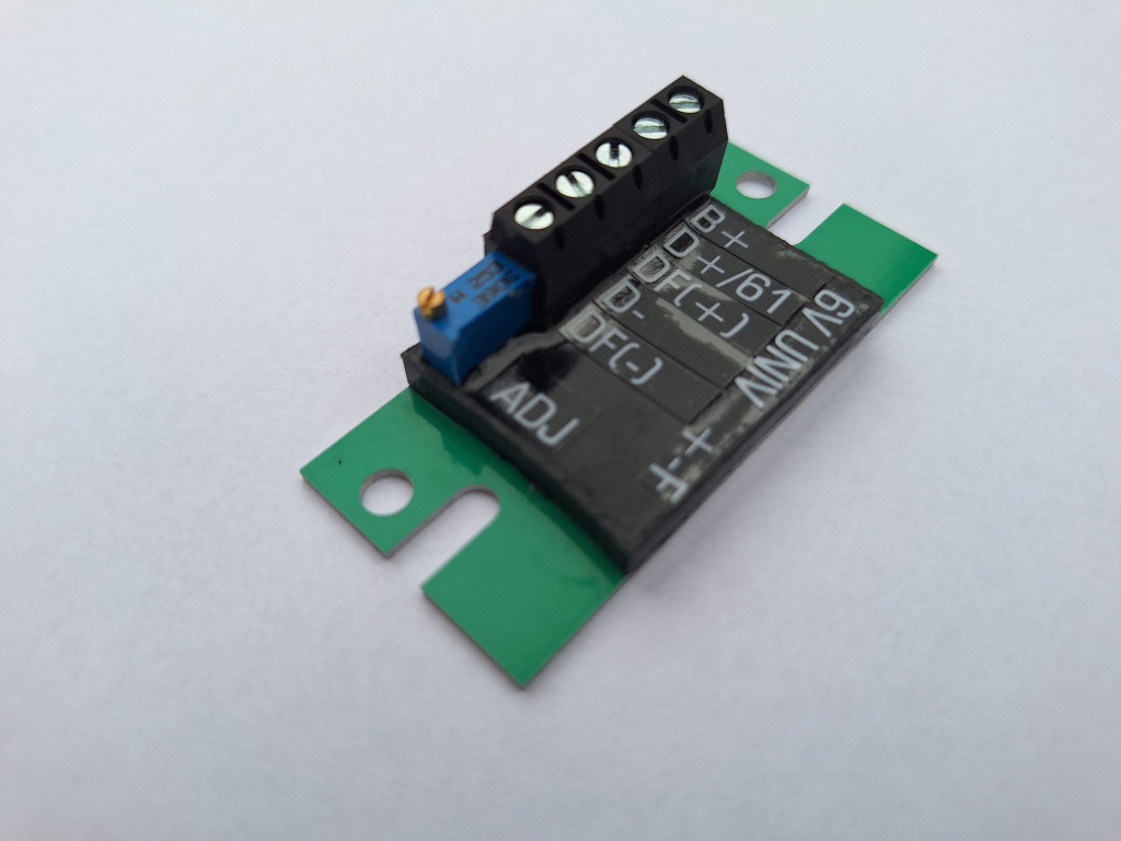
The aluminum-based universal regulator module is designed in an extremely small compact size, primarily to allow installation inside the original regulator housing, ensuring compliance for oldtimer certification. The regulator should be mounted onto a metal part of the original regulator to facilitate heat dissipation.
If oldtimer compliance is not a requirement, the regulator can be installed independently. However, it must still be mounted on a metal surface to transfer the generated heat.
For improved thermal conductivity, it is recommended to apply thermal paste or silicone grease to the bottom of the regulator.
For proper installation and operation:
After installing and wiring the regulator, or after any disassembly affecting the charging system or dynamo repair, the dynamo must be polarized! This should be done while the dynamo, the regulator and battery are already connected but before starting the engine. To polarize, momentarily connect the D+ and B+ terminals of the regulator or dynamo using a single wire for 1-2 seconds.
While the engine is running, disconnecting the battery is strictly prohibited, and the regulator's B+ terminal must never be left without voltage.
There should be no fuse between the regulator B+ and the battery B+.
To eliminate misleading and harmful voltage differences affecting the regulator’s operation, a direct-wired grounding circuit is required between:
- The engine block housing
- The frame
- The battery negative terminal
- The voltage regulator D- terminal
Use appropriately sized (2-2.5 mm²) wires for both the positive and negative sides of the charging circuit.
If adjustment of the regulator is necessary, it should be set to 7.4-7.6V with the battery connected, fully charged, and in good condition, and all consumers turned off to ensure accurate measurement results.
The charging indicator bulb must be of factory-specified wattage or higher (max. 4W). A LED alone is not sufficient.
If the original regulator has a separately positioned auxiliary coil or resistor (located in the dynamo housing, ignition base plate, or the stator excitation coil group), it must be disconnected before commissioning. Failure to do so may disrupt or damage the new regulator.
Ensure correct battery polarity when connecting!
When charging the installed battery with an external mains charger, always disconnect either the positive or negative battery cable to prevent damage from voltage spikes in older chargers.
Always leave one of the DF+ or DF- terminals unconnected, depending on the internal wiring of the dynamo.